

How To Use A Taper Jig

Drill chucks mounted by Jacobs tapers onto arbors with Morse tapers for the spindle.

Spindle nose on a lathe headstock. The small-scale female taper is a Morse taper to take a lathe center or a tool such as a twist drill. The large male taper takes a lathe chuck, which is retained past the large nut.
A automobile taper is a system for securing cut tools or toolholders in the spindle of a machine tool or ability tool. A male fellow member of conical form (that is, with a taper) fits into the female socket, which has a matching taper of equal angle.
Nigh all auto tool spindles, and many power tool spindles, have a taper every bit their master method of attachment for tools. Fifty-fifty on many drill presses, handheld drills, and lathes, which have chucks (such as a drill chuck or collet chuck), the chuck is attached by a taper. On drills, drill presses, and milling machines, the male member is the tool shank or toolholder shank, and the female socket is integral with the spindle. On lathes, the male may belong to the tool or to the spindle; spindle noses may accept male tapers, female tapers, or both.
Explanation [edit]
Machine tool operators must be able to install or remove tool bits quickly and easily. A lathe, for case, has a rotating spindle in its headstock, to which one may want to mount a spur bulldoze or work in a collet. Some other example is a drill printing, to which an operator may desire to mount a bit directly, or using a drill chuck.
Nigh all milling machines, from the oldest manual machines up to the almost modern CNC machines, use tooling that is piloted on a tapered surface.
The machine taper is a simple, low-cost, highly repeatable, and versatile tool mounting system. It provides indexability, as tools tin can be quickly changed but are precisely located both concentrically and axially by the taper. Information technology besides allows high ability transmission across the interface, which is needed for milling.
Automobile tapers tin can be grouped into self-holding and self-releasing classes. With self-belongings tapers, the male and female person wedge together and bind to each other to the extent that the forces of drilling tin exist resisted without a drawbar, and the tool volition stay in the spindle when idle. It is driven out with a wedge when a tool change is needed. Morse and Jacobs tapers are an case of the cocky-holding diverseness. With self-releasing tapers, the male will not stick in the female without a drawbar holding it there. All the same, with good drawbar strength, information technology is very solidly immobile. NMTB/CAT, BT and HSK are examples of the self-releasing variety.
For light loads (such as encountered by a lathe tailstock or a drill press), tools with cocky-property tapers are simply slipped onto or into the spindle; the pressure of the spindle confronting the workpiece drives the tapered shank tightly into the tapered hole. The friction across the unabridged surface area of the interface provides a large amount of torque transmission, and so that splines or keys are not required.
For use with heavy loads (such as encountered by a milling machine spindle), in that location is usually a key to prevent rotation and/or a threaded section, which is engaged by a drawbar that engages either the threads or the head of a pull stud that is screwed into them. The drawbar is so tightened, drawing the shank firmly into the spindle. The draw-bar is of import on milling machines equally the transverse force component would otherwise cause the tool to wobble out of the taper.
All motorcar tapers are sensitive to chips, nicks (dents), and dirt. They will not locate accurately, and the cocky-holding diversity will not concur reliably, if such problems interfere with the seating of the male into the female with business firm contact over the whole conical surface. Machinists are trained on keeping tapers clean and treatment them in ways that prevent them from being nicked by other tools. CNC tool-irresolute cycles usually include a compressed-air boom while one toolholder is existence swapped with the adjacent. The air nail tends to blow away chips that might otherwise finish upward interfering betwixt the toolholder and spindle.
Use [edit]
Tools with a tapered shank are inserted into a matching tapered socket and pushed or twisted into place. They are then retained by friction. In some cases, the friction fit needs to exist made stronger, as with the use of a drawbar, substantially a long bolt that holds the tool into the socket with more strength than is possible by other means.
Circumspection needs to be exercised in the usual drilling automobile or lathe situation, which provides no drawbar to pull the taper into engagement, if a tool is used requiring a high torque merely providing footling axial resistance. An example would be the use of a large diameter drill to slightly enlarge an existing pigsty. In this situation, there may be considerable rotary loading. In contrast, the cut action volition crave very little thrust or feed force. Thrust helps to keep the taper seated and provides essential frictional coupling.
The tang is not engineered to withstand twisting forces which are sufficient to crusade the taper to slip, and will often break off in this situation. This will permit the tool to spin in the female person taper, which is likely to damage it. Morse taper reamers are bachelor to alleviate minor damage.
Tapered shanks "stick" in a socket best when both the shank and the socket are clean. Shanks tin be wiped clean, simply sockets, being deep and inaccessible, are best cleaned with a specialized taper cleaning tool which is inserted, twisted, and removed.
Tapered shank tools are removed from a socket using different approaches, depending on the design of the socket. In drill presses and similar tools, the tool is removed by inserting a wedge shaped block of metal called a "migrate" into a rectangular shaped cantankerous pigsty through the socket and tapping it. Every bit the cantankerous section of the drift gets larger when the drift is driven further in, the result is that the drift, begetting confronting the foremost border of the tang, pushes the tool out. In many lathe tailstocks, the tool is removed by fully withdrawing the quill into the tailstock, which brings the tool up against the terminate of the leadscrew or an internal stud, separating the taper and releasing the tool. Where the tool is retained by a drawbar, as in some factory spindles, the drawbar is partially unthreaded with a wrench and and so tapped with a hammer, which separates the taper, at which point the tool can be farther unthreaded and removed. Some manufacturing plant spindles accept a convict drawbar which ejects the tool when actively unscrewed past the loose stage; these do non crave tapping. For simple sockets with open admission to the back cease, a migrate punch is inserted axially from behind and the tool tapped out.
Types [edit]
There are many standard tapers, which differ based on the following:
- the diameter at the minor terminate of the truncated cone ("the small-scale diameter")
- the diameter at the large end of the truncated cone ("the major diameter") and
- the axial distance betwixt the ii ends of the truncated cone.
The standards are grouped into families that may include unlike sizes. The taper within a family unit may or may not be consistent. The Jarno and NMTB tapers are consistent, only the Jacobs and Morse families vary.
In that location are adaptors bachelor to allow the use of i type of taper tooling, e.g. Morse, on a machine with a unlike taper, e.1000. R8 or vice versa, and simpler adaptors consisting of an externally and internally tapered sleeve to permit a small Morse tool to be used in a car of larger diameter.
One of the first uses of tapers was to mount drill bits directly to machine tools, such as in the tailstock of a lathe, although later drill chucks were developed that held parallel shank drill bits.
Brownish and Sharpe [edit]
Brown & Sharpe tapers, standardized past the company of the same name, are an alternative to the more-commonly seen Morse taper. Like the Morse, these have a series of sizes, from 1 to 18, with vii, nine and 11 being the about mutual. Actual taper on these lies within a narrow range close to .500 inches per foot.
| Size | Lg. Dia. | Sm. Dia. | Length | Taper (in/ft) | Taper (in/in) |
|---|---|---|---|---|---|
| 1 | 0.2392 | 0.2000 | 0.94 | 0.5020 | 0.04183 |
| 2 | 0.2997 | 0.2500 | 1.19 | 0.5020 | 0.04183 |
| 3 | 0.3753 | 0.3125 | 1.50 | 0.5020 | 0.04183 |
| 4 | 0.4207 | 0.3500 | 1.69 | 0.5024 | 0.04187 |
| five | 0.5388 | 0.4500 | 2.13 | 0.5016 | 0.04180 |
| half dozen | 0.5996 | 0.5000 | 2.38 | 0.5033 | 0.04194 |
| vii | 0.7201 | 0.6000 | 2.88 | 0.5010 | 0.04175 |
| eight | 0.8987 | 0.7500 | 3.56 | 0.5010 | 0.04175 |
| 9 | ane.0775 | 0.9001 | iv.25 | 0.5009 | 0.04174 |
| 10 | 1.2597 | 1.0447 | 5.00 | 0.5161 | 0.04301 |
| 11 | 1.4978 | ane.2500 | 5.94 | 0.5010 | 0.04175 |
| 12 | 1.7968 | one.5001 | 7.13 | 0.4997 | 0.04164 |
| 13 | 2.0731 | 1.7501 | seven.75 | 0.5002 | 0.04168 |
| 14 | two.3438 | 2.0000 | viii.25 | 0.5000 | 0.04167 |
| 15 | two.6146 | 2.2500 | 8.75 | 0.5000 | 0.04167 |
| 16 | ii.8854 | 2.5000 | 9.25 | 0.5000 | 0.04167 |
| 17 | 3.1563 | two.7500 | 9.75 | 0.5000 | 0.04167 |
| 18 | iii.4271 | 3.0000 | 10.25 | 0.5000 | 0.04167 |
Jacobs [edit]
The Jacobs Taper (abbreviated JT) is usually used to secure drill printing chucks to an arbor. The taper angles are non consistent varying from 1.41° per side for No. 0 (and the obscure #2+ 1⁄ii ) to 2.33° per side for No. 2 (and No. 2 short).
In that location are as well several sizes between No. 2 and No. 3: No. 2 short, No. half-dozen and No. 33.
| Taper | Small Cease | Big Cease | Length |
|---|---|---|---|
| No. 0 | 0.22844 in (5.8024 mm) | 0.2500 in (six.3500 mm) | 0.43750 in (11.113 mm) |
| No. 1 | 0.33341 in (8.4686 mm) | 0.3840 in (9.7536 mm) | 0.65625 in (16.669 mm) |
| No. 2 | 0.48764 in (12.386 mm) | 0.5590 in (14.199 mm) | 0.87500 in (22.225 mm) |
| No. ii Brusk | 0.48764 in (12.386 mm) | 0.5488 in (13.940 mm) | 0.75000 in (xix.050 mm) |
| #ii+ one⁄2 | 0.625 in (15.875 mm) | 0.677 in (17.196 mm) | 1.055 in (26.797 mm) |
| No. 3 | 0.74610 in (eighteen.951 mm) | 0.8110 in (twenty.599 mm) | ane.21875 in (thirty.956 mm) |
| No. 4 | 1.0372 in (26.345 mm) | 1.1240 in (28.550 mm) | 1.6563 in (42.070 mm) |
| No. five | ane.3161 in (33.429 mm) | one.4130 in (35.890 mm) | 1.8750 in (47.625 mm) |
| No. half dozen | 0.6241 in (15.852 mm) | 0.6760 in (17.170 mm) | 1.0000 in (25.400 mm) |
| No. 33 | 0.5605 in (fourteen.237 mm) | 0.6240 in (15.850 mm) | 1.0000 in (25.400 mm) |
Jarno [edit]
Jarno tapers use a greatly simplified scheme. The rate of taper is 1:20 on diameter, in other words 0.600" on diameter per foot, .050" on diameter per inch. Tapers range from a Number 2 to a Number xx. The bore of the big finish in inches is ever the taper size divided by eight, the minor terminate is ever the taper size divided by 10 and the length is the taper size divided by two. For example, a Jarno No. 7 measures 0.875" (7/8) beyond the big end. The small-scale end measures 0.700" (7/ten) and the length is three.5" (7/2).
The system was invented past Oscar J. Beale of Brown & Sharpe.
| Taper | Big end | Small end | Length | Taper/ ft | Taper/ in | Angle from center/° |
|---|---|---|---|---|---|---|
| No. two | 0.2500 | 0.2000 | one.00 | .6000 | .0500 | 1.4321 |
| No. iii | 0.3750 | 0.3000 | 1.fifty | .6000 | .0500 | 1.4321 |
| No. 4 | 0.5000 | 0.4000 | 2.00 | .6000 | .0500 | one.4321 |
| No. 5 | 0.6250 | 0.5000 | 2.l | .6000 | .0500 | 1.4321 |
| No. 6 | 0.7500 | 0.6000 | 3.00 | .6000 | .0500 | 1.4321 |
| No. 7 | 0.8750 | 0.7000 | three.50 | .6000 | .0500 | 1.4321 |
| No. viii | i.0000 | 0.8000 | iv.00 | .6000 | .0500 | 1.4321 |
| No. 9 | 1.1250 | 0.9000 | iv.fifty | .6000 | .0500 | 1.4321 |
| No. 10 | 1.2500 | 1.0000 | five.00 | .6000 | .0500 | ane.4321 |
| No. 11 | 1.3750 | one.1000 | v.50 | .6000 | .0500 | 1.4321 |
| No. 12 | 1.5000 | 1.2000 | vi.00 | .6000 | .0500 | 1.4321 |
| No. xiii | 1.6250 | 1.3000 | 6.50 | .6000 | .0500 | 1.4321 |
| No. fourteen | ane.7500 | 1.4000 | 7.00 | .6000 | .0500 | 1.4321 |
| No. 15 | 1.8750 | 1.5000 | 7.l | .6000 | .0500 | 1.4321 |
| No. 16 | 2.0000 | 1.6000 | 8.00 | .6000 | .0500 | 1.4321 |
| No. 17 | 2.1250 | 1.7000 | viii.l | .6000 | .0500 | 1.4321 |
| No. 18 | two.2500 | 1.8000 | 9.00 | .6000 | .0500 | 1.4321 |
| No. nineteen | ii.3750 | ane.9000 | ix.l | .6000 | .0500 | 1.4321 |
| No. 20 | two.5000 | 2.0000 | ten.00 | .6000 | .0500 | 1.4321 |
Morse [edit]

The Morse taper was developed past Stephen A. Morse, based in New Bedford, Massachusetts, in the mid-1860s.[1] Since then, it has evolved to cover smaller and larger sizes and has been adopted every bit a standard by numerous organizations, including the International Organization for Standardization (ISO) equally ISO 296 and the High german Constitute for Standardization (DIN) as DIN 228-1. It is one of the most widely used types, and is peculiarly common on the shank of taper-shank twist drills and machine reamers, in the spindles of industrial drill presses, and in the tailstocks of lathes. The taper bending of the Morse taper varies somewhat with size merely is typically 1.49 degrees (around 3 degrees included).
Some modular orthopedic total hip implants use a Morse taper to mate components together.[2] Similarly, some dental implants utilize a Morse taper to connect components.[3]
Sizes [edit]
Morse tapers come in eight sizes identified by whole numbers between 0 and 7, and one one-half-size (iv 1/ii - very rarely establish, and not shown in the tabular array). Often the designation is abbreviated as MT followed by a digit, for example a Morse taper number 4 would exist MT4. The MT2 taper is the size about often found in drill presses upward to 1⁄2 " chapters. Stub (brusque) versions, the same taper bending merely a little over half the usual length, are occasionally encountered for the whole number sizes from 1 through v. There are standards for these, which amongst other things are sometimes used in lathe head stocks to preserve a larger spindle through-hole.
End types [edit]
Morse tapers are of the self-property variety, and can have three types of ends:
- tang (illustrated) to facilitate Positive bulldoze, preventing slippage[4]
- threaded to exist held in identify with a drawbar
- apartment (no tang or threaded section)
Self-holding tapers rely on a heavy preponderance of axial load over radial load to transmit high torques. Problems may ascend using large drills in relation to the shank, if the pilot hole is also large. The threaded manner is essential for any sideloading, particularly milling. The just exception is that such unfavourable situations can exist false to remove a jammed shank. Permitting chatter will aid release the grip. The acute (narrow) taper angle can effect in such jamming with heavy axial loads, or over long periods.
End-milling cutters with a Morse taper shank with a tang are occasionally seen: for security these must exist used with a C-collar or like, fitting into the neck betwixt cutter and shank, and pulling back against the big stop of the taper
The taper itself is roughly 5/8" per foot, but verbal ratios and dimensions for the diverse sizes of tang blazon tapers are given below.
Dimensions [edit]

| Morse taper number | Taper | A | B (max) | C (max) | D (max) | E (max) | F | G | H | J | K |
|---|---|---|---|---|---|---|---|---|---|---|---|
| 0 | 1:19.212 | 9.045 | 56.5 | 59.5 | x.5 | vi | four | 1 | 3 | 3.9 | 1° 29' 27" |
| 1 | 1:20.047 | 12.065 | 62 | 65.5 | thirteen | 8.7 | 5 | i.2 | 3.5 | 5.2 | 1° 25' 43" |
| two | 1:twenty.020 | 17.780 | 75 | eighty | sixteen | xiii.5 | 6 | 1.half dozen | 5 | 6.iii | 1° 25' fifty" |
| 3 | i:xix.922 | 23.825 | 94 | 99 | 20 | 18.5 | vii | 2 | 5 | 7.9 | 1° 26' xvi" |
| 4 | 1:nineteen.254 | 31.267 | 117.5 | 124 | 24 | 24.5 | viii | 2.v | 6.v | eleven.9 | one° 29' xv" |
| 5 | 1:nineteen.002 | 44.399 | 149.v | 156 | 29 | 35.vii | ten | 3 | 6.v | xv.9 | 1° 30' 26" |
| 6 | 1:19.180 | 63.348 | 210 | 218 | forty | 51 | 13 | 4 | viii | nineteen | 1° 29' 36" |
| vii | 1:19.231 | 83.058 | 285.75 | 294.1 | 34.9 | – | – | 19.05 | – | 19 | 1° 29' 22" |
B Tapers [edit]
B-series tapers are a DIN standard (DIN 238) typically used for plumbing equipment chucks on their arbors, like the older Jacobs taper series. Each taper in the B-serial is finer the small or big end of a Morse taper:
- B10 = small cease of MT1 (D = 10.095 mm)
- B12 = large end of MT1 (D = 12.065 mm)
- B16 = modest end of MT2 (D = 15.733 mm)
- B18 = large stop of MT2 (D = 17.780 mm)
- B22 = small end of MT3 (D = 21.793 mm)
- B24 = big end of MT3 (D = 23.825 mm)
The number after the B is the bore (D) of the large end of the taper to the nearest mm, and 'nigh' 1mm larger than the large end of the socket (~2mm in the example of B22 and B24) [5] [6] [7]
NMTB taper family [edit]

Toolholder for milling machine with True cat-40 taper.
The National Auto Tool Builders Association (at present called the Clan for Manufacturing Technology) defined a steep taper that is commonly used on milling machines. The taper is variously referred to as NMTB, NMT or NT. The taper is 3.500 inches per pes and is also referred to equally "7 in 24" or seven/24; the computed angle is 16.5943 degrees.[viii] All NMTB tooling has this taper but the tooling comes in different sizes: NMTB-10, xv, 20, 25, xxx, 35, 40, 45, 50 and 60. These tapers were patently also specified in ASA (now ANSI) B5.10-1943.
NMTB is a "self releasing" or "fast" taper. Unlike the more astute self holding tapers above, such tapers are not designed to transmit high torque; high torques are carried past driving keys engaging slots on the flange.[9] [ten] The purpose is to allow a quick and easy change between different tools (either automatically or by hand) while ensuring the tool or toolholder will be tightly and rigidly connected to the spindle, and accurately coaxial with it. The larger terminate side by side to the tool makes for more rigidity than is possible with Morse or R8 tapers fitted to comparable machines.
Patent 1794361 (filed 25 March 1927) describes milling machine spindle and tool shapes using a steep taper.[11] The patent was assigned to Kearney & Trecker Corporation, Brown & Sharpe, and Cincinnati Milling Machine Company. The patent wanted a taper that would freely release the tool and found that a taper of iii.5 in 12 had that belongings.[12] The patent likewise used the keys and slots and a tail on the tool shank to forbid the tool shank from falling out of a horizontal mill's spindle while the operator connected the drawbar.[12]
ANSI B5.18-1972 specifies some essential dimensions for milling machine spindles and tool shanks using taper sizes 30, 40, 45, l, lx.[xiii] The specifications draw the position of the driving fundamental and flange and the thread of the describe-in bolt that holds the shank in the spindle.
The tooling is referred to as Quick Change; National Automobile Tool Builders' Association, 1927; NMTB; American Standard Machine Taper, ANSI B5.18; DIN 2080 / IS 2340; ISO R 290-2583.[14] In that location are slight variations in threads and flanges (JIS B 6339: MAS 403); and the European standards (e.1000., ISO taper) use metric draw threads.
The NMTB tool shanks had the 7 in 24 taper, but they as well had a constant diameter tail (pilot) at the end of the shank that was described in the 1927 patent. Subsequent design variations dropped the tail (making the shank shorter) and put a V-groove in the flange that aided automated tool changing. Modern designs started using ability drawbars that gripped pull studs (besides known as retention knobs) that were screwed into the tool shank rather than screw-in drawbars. The ability drawbar would grip the pull stud rather than screwing into the tool shank.
The more mod toolholder designs became known as the Caterpillar "V-Flange", CAT, V-Flange, ANSI B5.l, SK, ISO, International (INT), BT, ISO 7388-one, DIN 69871, NFE 62540. Again, there are slight variations in the tooling.[xiv] Although the bones taper dimensions are the aforementioned, at that place are differences in the flanges, draw-in thread sizes, and pull studs; the international versions use metric sizes.
HSK taper [edit]
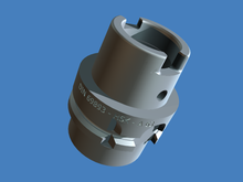
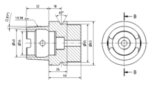
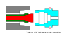
Animation of HSK toolholder
HSK toolholders were adult in the early 1990s. HSK stands for de:Hohlschaftkegel; High german for "hollow shank tapers".
Steep tapers tend to loosen at loftier speed, every bit their solid shanks are stiffer than the spindles they fit into, and then under loftier centrifugal strength, the spindle expands more than than the toolholder which changes the overall length: That is, as the spindle 'expands' the toolholder tends to move deeper into the spindle in the z-axis which tin can cause the production of parts that are out-of-tolerance. HSK'south hollow shank is deliberately sparse and flexible, and so it expands more than the spindle and tightens when rotating at high speed. Furthermore, the HSK holder is dual contact: It engages with the spindle on both the taper and the top of the flange which prevents axial movement when thermal growth and/or centrifugal strength of the spindle occurs.
The flexibility is also used to provide accurate axial location. An HSK toolholder has both a tapered shank, and a flange with a mating surface. The shank is brusque (nigh half every bit long as other machine tapers), with a shallow taper (a ratio of ane:ten), and slightly too large to permit the flange to seat fully in the socket. The thin walls, short shank and shallow taper provide a large opening in the back of the tool. An expanding collet fits in there, and mates with 30° chamfer within the shank. As the drawbar retracts, information technology expands the collet and pulls the shank back into the socket, compressing the shank until the flange seats against the front of the spindle. This provides a strong, repeatable connectedness because it utilizes the centrifugal force inside the spindle. Every bit centrifugal forces increase the expanding collet within the HSK forces the walls of the toolholder shank to stay in contact with the spindle wall.
The HSK design was adult as a nonproprietary standard. The working grouping that produced the HSK standard consisted of representatives from academia, the Association of High german Tool Manufacturing and a group of international companies and end users. The results were the German language DIN standards 69063 for the spindle and 69893 for the shank. The HSK working group did non adopt a specific product blueprint, but rather a set up of standards that defined HSK toolholders for different applications. The group defined a full of half-dozen HSK shank forms, in 9 sizes.
Sizes are identified past the diameter of the shank'south flange in millimeters. These diameters are taken from the R10′ serial of preferred numbers, from 25 to 160 mm.
Today, the shank forms are designated by the letters A through F and T. The main differences betwixt the forms are the positions of the bulldoze slots, gripper-locating slots, coolant holes and the expanse of the flange.
A is the bones class. The B-form shank is a variant for high-torque applications, and has a flange one size larger relative to its shaft bore. (Thus, an A-40 shank will fit into a B-50 socket.)
Forms C and D are simplified variants of A and B for transmission use, eliminating features to accommodate automatic tool changers like a V-groove and associated orientation slots, and a recess for an RFID chip.
Forms East and F flanges and tapers are similar to forms A and B, but designed for very loftier speed machining (20,000 rpm and up) of calorie-free materials by eliminating all asymmetric features to minimize imbalance and vibration.
ASME B5.62 "Hollow Taper Tooling With Flange-Face Contact"[15] and ISO 12164-3:2014 "Dimensions of shanks for stationary tools"[16] include an additional form T, which is bidirectionally compatible with form A, only has a much tighter tolerance on the widths of the keys and keyways used for angular alignment. This permits non-rotating lathe tooling to exist held accurately.[17]
An HSK connection depends on a combination of axial clamping forces and taper-shank interference. All these forces are generated and controlled by the mating components' pattern parameters. The shank and spindle both must have precisely mating tapers and faces that are square to the taper's axis. There are several HSK clamping methods. All use some mechanism to amplify the clamping activity of equally spaced collet segments. When the toolholder is clamped into the spindle, the drawbar forcefulness produces a house metal-to-metallic contact between the shank and the ID of the clamping unit of measurement. An additional application of drawbar force positively locks the ii elements together into a articulation with a high level of radial and axial rigidity. As the collet segments rotate, the clamping machinery gains centrifugal force. The HSK design actually harnesses centrifugal force to increment joint strength. Centrifugal force also causes the thin walls of the shank to deflect radially at a faster charge per unit than the walls of the spindle. This contributes to a secure connection by guaranteeing strong contact betwixt the shank and the spindle. The automotive and aerospace industries are the largest users of HSK toolholders. Another industry that is seeing increasing utilize is the mold and die manufacture.
R8 [edit]
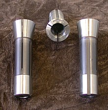
This taper was designed by Bridgeport Machines, Inc. for use in its milling machines. R8 tapers are not cocky-property, and then they require a drawbar extending upward through the spindle to the pinnacle of the machine to forestall loosening when lateral forces are encountered. They are also keyed (run into image) to prevent rotation during insertion and removal, although it is the taper that transmits torque in use. The drawbar thread is typically 7⁄sixteen ″–twenty tpi (UNF). The angle of the cone is xvi°51′ (xvi.85°) with an OD of 1.25″ and a length of 15⁄16 ″.[18] (source, Bridgeport Manufacturer) The diameter of the parallel locating portion is non a "partial inch" size like the other dimensions and is 0.949″ to 0.9495″.
Tools with an R8 taper are inserted directly into the motorcar'south spindle. R8 collets are typically used to hold tooling with round shanks, although any shape can be held if the collet has the corresponding shape cutting in it. The collets accept a precision diameter with axial compression slots for holding cutting tools and are threaded for the drawbar. The R8 system is commonly used with collets ranging in size from one⁄eight ″ to three⁄4 ″ in diameter or tool holders with the aforementioned or slightly larger diameters. The collets or tool holders are placed directly into the spindle and the drawbar is tightened into the top of the collet or tool holder from in a higher place the spindle. Other tools such every bit drill chucks, wing cutters, indexable insert cutters, etc. may take an R8 taper shank congenital into or added to the tool.
The R8 taper is commonly encountered on Bridgeport and similar turret mills from the USA, or on (very mutual) copies of these mills from elsewhere. The popularity is due in large office to the success of Bridgeport and other mills that were closely modeled afterwards it and produced throughout much of the 20th century.
See besides [edit]
- Chuck
- Collet
References [edit]
- ^ Morse Cutting Tools History Archived 10 May 2015 at the Wayback Car.
- ^ Schramm, Thousand.; Wirtz, D. C.; Holzwarth, U.; Pitto, R. P. (April 2000). "The Morse taper junction in modular revision hip replacement—a biomechanical and retrieval analysis". Biomed Tech (Berl). 45 (4): 105–9. doi:10.1515/bmte.2000.45.4.105. PMID 10829545. S2CID 21186374.
- ^ Shafie, Hamid R. (9 July 2014). Clinical and Laboratory Manual of Dental Implant Abutments. John Wiley & Sons. ISBN9781118928530.
- ^ Approximate, Arthur W (1940–1950s). Applied science Workshop Practice (New and Revised ed.). Caxton. pp. vol i 137.
- ^ "Archived copy" (PDF). Archived from the original (PDF) on 30 December 2019. Retrieved 30 December 2019.
{{cite web}}: CS1 maint: archived copy as championship (link) - ^ "Drill Chuck Taper Dimensions".
- ^ "Archived copy" (PDF). Archived from the original (PDF) on 2 July 2019. Retrieved two July 2019.
{{cite web}}: CS1 maint: archived copy as title (link) - ^ The angle of the cone is 2 atan(seven/48).
- ^ Burlingame, Luther D. (December 1918), "Standards for Large Taper Shanks and Sockets", Periodical of the American Society of Mechanical Engineers, forty (12): 1014–1016,
As shown in Table i, the well-established tapers for shanks and sockets now in use vary from 1⁄2 in. to 1 in. or more per ft., the tendency being to use a somewhat steeper taper for the larger than for the small sizes, perhaps because with small tapers, the liability to slip produced by the work is non so neat and the "bite" of the taper when forced into the socket is sufficient to secure constructive driving. In the larger sizes, tenons or tongues must be provided to aid in driving and in the all the same larger sizes keys of some course are needed, as, unless the angle of taper is very slight, the tenons are liable to be twisted off. When such auxiliary means of driving is provided the taper can be made steeper, giving the advantage that the parts can be more easily separated.
- ^ Armitage et al. 1931, p. 3 stating, "The [tool shank] is now firmly coupled with the spindle, the complementary tapered portions serving to insure accurate axial alignment while the complementary keys and slots serve to drive the [tool shank] from the spindle in either management of rotation and the [drawbar] retains the [tool shank] firmly seated in such position."
- ^ United states 1794361, Armitage, Joseph B.; Kearney, Edward J. & Graves, Benjamin P. et al., "Milling Machine Spindle and Tool", published 1931-03-03
- ^ a b Armitage et al. 1931, p. 2
- ^ Machinery's Handbook (22nd ed.), Industrial Press, 1987, pp. 1748–1752, ISBN0-8311-1155-0
- ^ a b "Machine Tool Shanks (Tapers)".
- ^ Hollow Taper Tooling With Flange-Confront Contact, ASME B5.62, American Society of Mechanical Engineers
- ^ ISO 12164-3:2014 "Hollow taper interface with flange contact surface—Part iii: Dimensions of shanks for stationary tools"
- ^ "What is HSK-T?" (PDF). NT Tool Co. 9 October 2014. Retrieved 9 February 2018.
- ^ Machine Tool Taper Dimensions: Bridgeport R8 & Deckel Int40
Sources
- Machine Tools – Self-holding tapers for tool shanks, ISO, 1991, ISO 296:1991
External links [edit]
- Cute Atomic number 26 Overview of Tapers
- Speedily Identify your Morse Taper
- http://world wide web.tools-n-gizmos.com/specs/Tapers.html (clarification of several tool holders)
- https://spider web.archive.org/web/20110316155700/http://world wide web.timgoldstein.com/CAD_CAM/tapers.htm (description of several tool holders)
- http://www.dlindustrial.com/profiles/blogs/steep-tapers-fast-tapers-at3-and-what-it-means (blog about belongings/releasing tapers and tolerance; claims taper not keys and slots do the driving; some errors)

How To Use A Taper Jig,
Source: https://en.wikipedia.org/wiki/Machine_taper
Posted by: moralesknoid1942.blogspot.com
0 Response to "How To Use A Taper Jig"
Post a Comment